DT Life Cycle
On this page

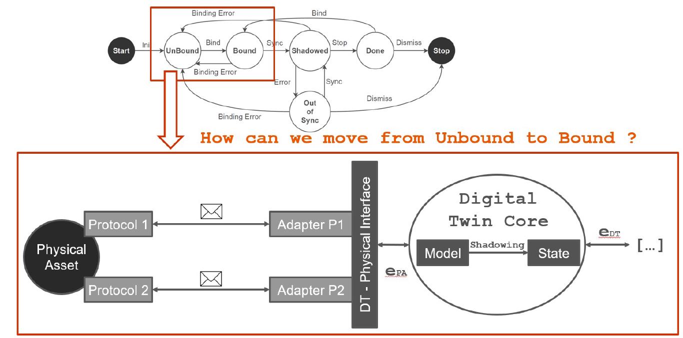
The modeling of the concept of DT includes also the definition and characterization of its life cycle. Based on the scientific literature, we model (and then map into the library) a life cycle with 5 states through which the DT goes from when it is executed to when it is stopped. The previous Figure shows a graphical representation of the life cycle with the following steps:
- Operating & Not Bound: this is the state in which the DT is located following the initialization phase, indicating that all internal modules of the DT are active but there is no association yet with the corresponding PA.
- Bound: this is the state in which the DT transitions following the correct execution of the binding procedure. The binding procedure allows to connect the two parts and enables bidirectional flow of events.
- Shadowed: this is the state reached by the DT when the shadowing process begins and its state is correctly synchronized with that of the PA.
- Out of Sync: this is the state that determines the presence of errors in the shadowing process. When in this state, the DT is not able to handle either state alignment events or those generated by the application layer.
- Done: this is the state that the DT reaches when the shadowing process is stopped, but the DT continues to be active to handle requests coming from external applications.
From Unbound to Bound
Taking into account the target reference Life Cycle the first point to address is how we can move from an UnBound state
to a Bound condition with respect to the relationship with the Physical Layer.

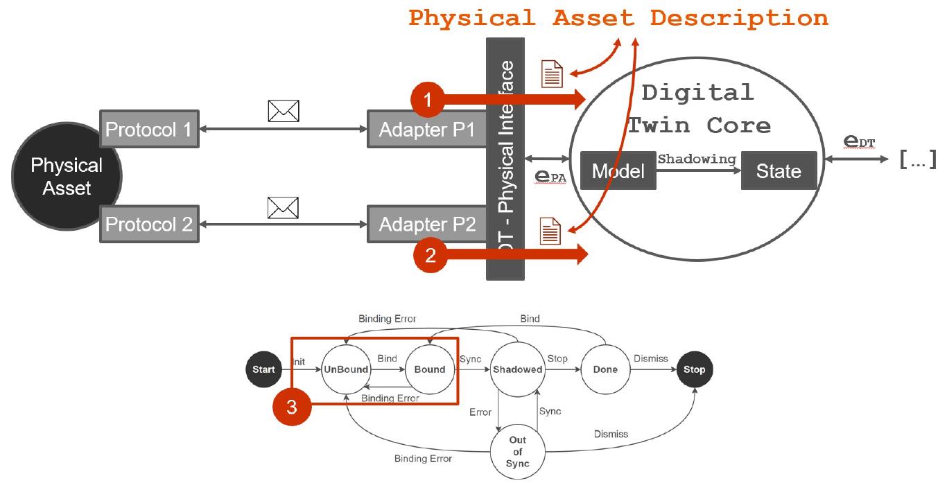
The previous Figure illustrates a simple scenario where a Physical Asset uses two protocols (P1 and P2) to communicate and it is connected to the Digital Twin through a DT’s Physical Interface enabled with two dedicated Adapters for protocol P1 and P2. In order to move from the Unbound to Bound state the DT should be aware of the description of the target asset with respect to the two protocols. For example through P1 the asset exposes telemetry data (e.g., light bulb status and energy consumption) while on P2 allows incoming action requests (e.g., turn on/off the light). The Digital Twin can start the shadowing process only when it is bound and has a description of the properties and capabilities of the associated physical counterpart. The schematic procedure is illustrated in the following Figure:

Involved steps are:
- The Adapter P1 communicates with the PA through Protocol 1 and provides a
Physical Asset Descriptionfrom its perspective - The Adapter P2 communicates with the PA through Protocol 2 and provides a
Physical Asset Descriptionfrom its perspective - Only when all Physical Adapters have been correctly bound (it may require time) to the Physical Asset and the associated
Physical Asset Descriptionshave been generated, the DT can move from UnBound to Bound
Main core aspects associated to the concept of Physical Asset Description (PAD) are the following:
- It is used to describe the list of properties, actions and relationships of a Physical Asset
- Each Physical Adapter generates a dedicated PAD associated to its perspective on the Physical Assets and its capabilities to read data and execute actions
- It is a responsibility of the DT to handle multiple descriptions in order to build the digital replica
- It will be used by the DT to handle the shadowing process and keep the digital replica synchronized with the physical counterpart
From Bound to Shadowed
Following the same approach described in the previous step we need to define a procedure to allow the DT to move from a Bound state
to a Shadowed condition where the twin identified the interesting capabilities of the Physical Asset that has to be
digitalized and according to the received Physical Asset Descriptions start the shadowing procedure to be synchronized with the physical world.

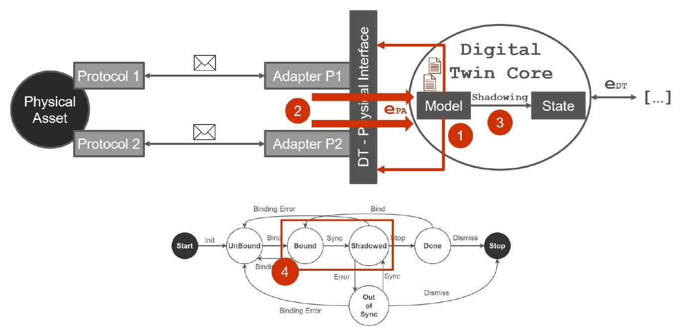
As schematically illustrated in the previous Figure, involved steps are:
- The Model defines which properties should be monitored on the Physical Asset and start observing them through the target adapters
- Involved Physical Adapters communicate with the Physical Asset, receive data and generate Events (ePA) to notify about physical property changes
- Received ePA will be used by the Digital Twin Model in order to run the Shadowing function and compute the new DT State
- The DT can move from the Bound to Shadowed phase until it is able to maintain a proper synchronization with the physical asset over time through its shadowing process and the generation and maintenance of the DT’s State
The Digital Twin State is structured and characterized by the following elements:
- A list of properties
- A list of actions
- A list of relationships
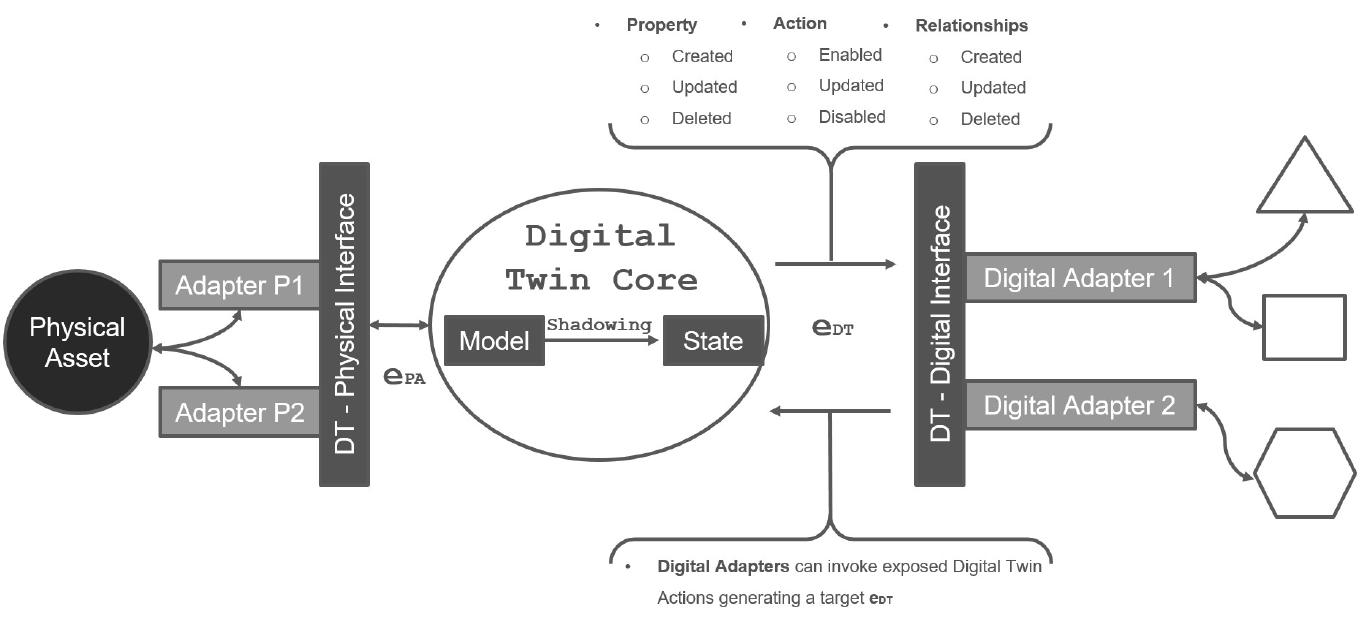
Listed elements can be directly associated to the corresponding element of the Physical Asset or generated by DT Model combining multiple physical properties, actions or relationships at the same time. The Digital Twin State can be managed through the Shadowing Function and exposes a set of methods for its manipulated. When there is a change in the DT State an event (eDT) will be generated
The manipulation of DT’s State generates a set of DT’s events (eDT) associated to each specific variation and evolution of the twin during its life cyle. These events are used by the Digital Interface and in particular by its Digital Adapters to expose the DT’s State, its properties and capabilities to the external digital world. At the same time, eDT can be used by Digital Adapters to trigger action on the DT and consequently to propagate (if acceptable and/or needed) the incoming request to the physical assets bound with the target DT. Supported events are illustrated in the following schema.
